767-400ER Flight Deck Upgrade
The 767-400ER flight deck upgrade is the latest advance toward the goal of a common look and feel in all Boeing airplane flight decks. Common controls, displays, functions, and procedures reduce flight-crew training requirements for transitioning among airplanes and simplify fleet maintenance. The flight deck looks similar to the one found on the 737-600/-700/-800/-900, 747-400, and 777, and it shares display layout and format commonality with these models. Offering an entirely new flight deck was not an option, because airline customers required that the 767-400 operate as part of their existing 757 and 767 fleets, with the same or common type rating currently in place. The 767-400ER flight deck meets this need and also provides a modern digital system with growth capacity to meet the requirements for future operations. The flight deck upgrade design also includes maintenance enhancements such as improved built-in test equipment (BITE), easier equipment access, and onboard software loading.
The main benefits offered through the 767-400ER flight deck upgrade are improvements in:
•Displays
•Controls
•Maintenance and Dispatch Reliability
•Training Requirements
•Capacity for Growth
•Summary
The large format display system (LFDS) is the most obvious change to the 767-400ER flight deck. The LFDS uses six 8- by 8-in liquid crystal displays (LCD) to display information about primary flight and navigation, engine indication and crew alerting system, synoptics, interface controls, and maintenance data.
Primary flight and navigation.
The outboard displays are used for primary flight information and replace the current electronic attitude direction indicators. The displays can be software configured to a customer-selected format for flexibility in integrating the 767-400ER into existing fleets.
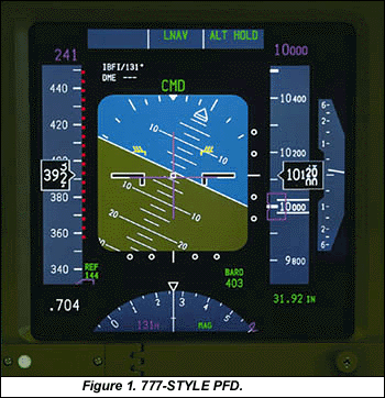
The baseline format is the 777-style primary flight display (PFD) that includes primary attitude, heading, altitude, vertical speed, airspeed, radio altitude, guidance information, speed and altitude reference, stall warning, navaid data, and mode annunciation (fig. 1).
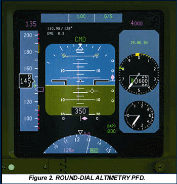
The PFD with round-dial altimetry provides the same information but incorporates a depiction of an analog altimeter and vertical speed indicator. Both formats are software selectable and can be loaded on board the airplane (fig. 2).
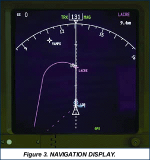
The inboard displays are primarily used for the navigation display (ND). The ND format is the same format used on the 777 and includes platform map, actual position versus planned position, heading (magnetic north and true north), ground track, waypoint depiction, navaid depiction, true airspeed, ground speed, wind data, traffic collision avoidance system (TCAS) (fig. 3), and ground proximity warning system.
Engine indication and crew alerting system (EICAS).
The EICAS display provides essentially the same information as the current system on primary and secondary display pages: engine parameters (N1 speed, engine gas temperature, N2 speed, fuel flow, oil pressure, oil temperature, oil quantity, engine vibration), crew alerting messages, exceedance logic, in-flight start envelope, and subsystem status (figs. 4 and 5).
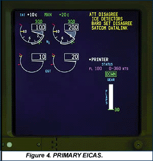
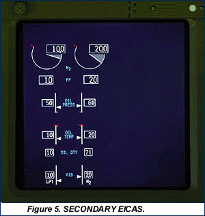
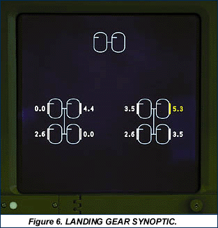
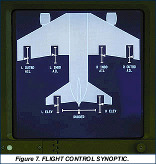
The upper EICAS display includes gear and flap position indicators that replace the current suite of analog dials and status lights. The system also provides enhanced flight controls and landing gear synoptic displays for more detailed information on system status.
Synoptics.
The inboard and center lower displays are configured as multifunction displays (MFD). To set each display unit, the flight crew can use the display select panel (DSP) to select any of five display formats: navigation display, secondary engine display, status page, landing gear synoptic (fig. 6), and flight control synoptic (fig. 7). Using the format select switch, the flight crew can also have the inboard display units show primary EICAS or PFD formats.
Interface controls.
The LFDS is controlled through various control panels and instruments: electronic flight instrument system (EFIS), DSP, multifunction control and display unit (MCDU), and standby instruments.
- The EFIS control panel is the primary interface for minimum altitude setting, barometric pressure reference, weather radar, TCAS, navigation display modes, and very high frequency omnirange (VOR) and automatic direction finder displays.
- The DSP control panel manages display modes for secondary EICAS, status messages, and synoptics. The DSP also provides multifunction display capability, allowing the operator to select the display format for the inboard and center lower displays. The display control panel provides brightness and source selection control for the data concentrator units. The display source select panel controls the display data source for the flight director, flight management computer (FMC), air data, inertial data, and VOR.
- If the EFIS control panel fails, the MCDU provides alternate control. Three MCDUs are available to interface with the FMC, the thrust management computer (TMC), the LFDS, and systems BITE (fig. 8). The MCDU also controls tuning for navigation aids, replacing VOR and instrument landing system tuning panels.
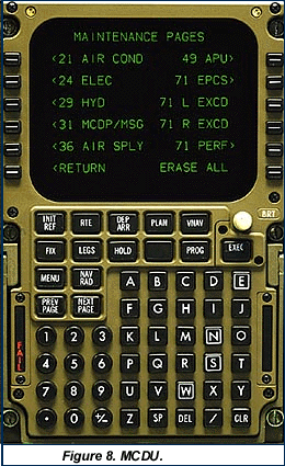
- The standby flight instruments are conventional analog instruments. The standby attitude reference is the same as the unit used in the 737-600/-700/-800/-900, and the standby altitude and airspeed references are the same units used in current-production 767 airplanes.
Maintenance data.
The LFDS provides easier access to a wider range of maintenance data. Maintenance pages are managed through the MCDUs and displayed on the MFDs. Nine individual pages are available: air conditioning; air supply; electrical; hydraulic; maintenance and maintenance control and display panel messages; auxiliary power unit; electronic propulsion control system; engine exceedance; and performance (fig. 9).
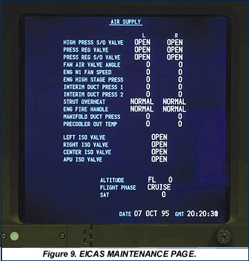
Any three maintenance pages can be displayed simultaneously using the MFD function, to provide maintenance personnel with more information and flexibility. The snapshot feature captures data for the appropriate maintenance page when a caution message is triggered. The page is stored and can be recalled on the ground to assist with maintenance troubleshooting by displaying the conditions at the time the caution message appeared.
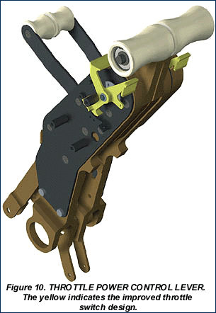
Most subsystem controls on the 767-400ER are the same as those on the 767-200/-300, with the overhead panel essentially unchanged. The flight control column is unchanged from the 767-300, but the control stand hardware more closely resembles the hardware on the 777. The thrust levels are 777 style, but they incorporate a new takeoff/go-around (TO/GA) switch that can be actuated by pressing the switch on the back of the thrust lever (current 767 procedure) or by using TO/GA paddles on the front of the thrust lever (777 procedure) (fig. 10). The flaps and speed brake controls are similar in appearance to the 777 controls and perform the same function as the 767-300 controls (fig. 11).
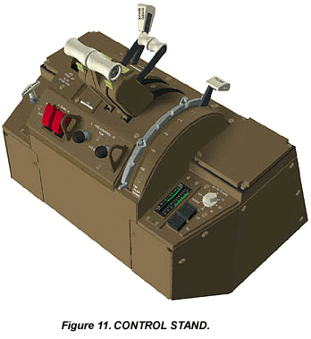
The landing gear control has been changed from a three-position mechanically actuated system to a two-position electrically actuated system. The center position (off) has been replaced with auto-off logic to remove hydraulic pressure from the landing gear after it is fully up and locked.
3. MAINTENANCE AND DISPATCH RELIABILITY
Design goals for the 767-400ER flight deck upgrade also included improvements in maintenance and dispatch. The number of individual components has been reduced and new, more reliable electronic components have replaced cathode ray tubes and mechanical displays. The system architecture provides increased redundancy and allows for component failures without loss or degradation of intended functions. The LFDS will operate normally with only one of three display process computers or only one data concentrator unit. The format management of the display units provides many options if a display unit fails. The addition of a third MCDU provides improved maintenance data accessibility and a warm spare for dispatch.
The upgrade also includes enhancements to provide improved BITE, easier access to equipment, and onboard software loading.
Improved BITE.
Wherever possible, BITE designs were improved and more systems are now compliant with the Boeing fault readout nomenclature standard. More BITE information is now accessible through the MCDU, and a complete review of EICAS resulted in fewer nuisance messages.
Easier access to equipment.
The flight deck structure has been redesigned to improve equipment access for easier removal and replacement. The dimmer units have been relocated below the floor, the display units use integral connectors, and environmental control system supply ducts are now an integral part of the cast panel. Most electrical wiring is routed through connectors on the electrical disconnect panel for improved access, and the use of digital interfaces has reduced the number of wires between the flight deck and electrical/electronics (E/E) bay. The control stand is now a self-contained unit with integral wiring. The autothrottle servos have been relocated in the control stand from below the floor.
Onboard software loading.
More systems can now be loaded with onboard software. A single-point data load switch in the flight deck or E/E bay allows software to be updated on the airplane rather than requiring the unit to be removed and shipped to a service center. More systems are compliant with ARINC 615, standardizing the load procedure and allowing airlines to update software on site for individual line replacement units.
The 767-400ER retains the same type rating as the 767-200/-300. Based on experience from training for the 737-600/-700/-800/-900, 767 crews require two to three days of differences training, including simulator time, when transitioning from a 767-200/-300 to the 767-400ER with the PFD/ND format. The time required for differences training for the PFD with round-dial altimetry format is further reduced from PFD/ND 767-400 airplanes. The same flight crews can operate the 767-400ER as part of an existing 757 or 767 fleet.
The 767-400ER flight deck upgrade allows operators to easily integrate the newest 767 into an existing fleet of 757 and 767 airplanes. The flight deck layout that resulted from the upgrade is consistent with the common look and feel envisioned for the entire Boeing fleet. This commonality reduces the time and cost required to transition flight crews among airplane models. In addition, the growth capacity built into the flight deck for the future addition of hardware and functionality allows operators to fly the airplane effectively and efficiently today and into the 21st century.
Reprinted from AERO magazine by permission of The Boeing Company
